Hm, well, it seems you are thinking to use a transmission gate to switch the pulse but it's not clear from your diagram what is on the input at the left of your R7, so I'm guessing it is the discharge pulse from your previous diagram. You might also consider explaining the diagram word pino. I thought I had replied to this message but I can't find the reply so I will summarize what might have just gone into the ether previously. For detecting a rapidly discharging analog pulse I would use a comparator (LM339 or op amp with very hi gain). One side of the comparator is the input. The other side of the comparator is optionally an adjustable voltage which is controlled by the microcontroller software, or you can make it a fixed value with a simple voltage divider. You can create the adjustable voltage by implementing software PWM (say, period of 20kHz) in the microcontroller and making it into an average with a simple 1st order filter. I don't think it would have enough ripple to matter much. The output of the comparator would be digital 1 or 0, depending on the threshold voltage you generate in software, which goes to a digital input pin on the microcontroller. Let's say you wire it such that the comparator goes to 1 at the detection of the peak. This creates a very fast digital 1 which is an interrupt to the microcontroller, which then executes an exact delay (40 usec - 10 usec = 30 usec spin delay time), and which then software triggers the microcontroller A/D to sample the voltage. Read the atmel chip datasheet closely to make sure the physics of the chip and the peripherals support what you are trying to do, in terms of timing (especially sample/hold time of the A/D peripheral). If you want to detect the negative-going pulse, then make a pair of the circuits I described, one for positive and one for negative, which is simple with a dual comparator IC. So in summary, my solution would be different than the circuit you have drawn. But I also didn't read the paper you posted previously so I might be misinterpreting your intention.
Don't forget that you will want to have a calibration algorithm which measures the impulse response of your own circuit. Presumably the user would run this on a known buffer, and the result would be saved as a calibration constant in EEPROM or Flash.
Don't forget that you will want to have a calibration algorithm which measures the impulse response of your own circuit. Presumably the user would run this on a known buffer, and the result would be saved as a calibration constant in EEPROM or Flash.
## Jonathan Cline ## jcline@ieee.org ## Mobile: +1-805-617-0223 ########################On 12/5/15 4:04 AM, Markos wrote:
Hi Jonathan,
I am continuing this project and I am currently studying this circuit:
www.c2o.pro.br/hackaguas/figuras/Condutivimetro_Pulso_Bipolar_04.png
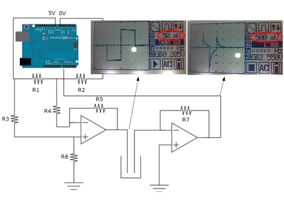
Now I'm trying to implement a circuit to sample the end of the second pulse.
For example, from a pulse of 40 microseconds make the reading of voltage only in the last 10 or 5 microseconds.
I plan to add a peak detector (attached figure).
What do you think?
Thanks for your attention,
Markos
On 03-12-2015 15:16, Jonathan Cline wrote:Solder the circuits, don't use a plastic breadboard, for conductivity measurements. I haven't used this technique that I remember, but have built conductivity tools.
## Jonathan Cline
## jcline@ieee.org
## Mobile: +1-805-617-0223
########################
On Tuesday, November 17, 2015 at 4:47:10 AM UTC-8, Markos wrote:Hi,
I'm trying to implement a conductivity meter with the Arduino board. My
intention is to keep the electronic circuit as simple as possible.
I'm only using a voltage divider as shown:
http://www.c2o.pro.br/hackaguas/figuras/ condutivimetro_00_bb.png
The alternating pulses are generated by switching the signals from pins
7 and 8 of Arduino:
http://www.c2o.pro.br/hackaguas/figuras/ condutividade_efeito_ frequencia_01.png
For now I'm using two steel wires as electrodes:
http://www.c2o.pro.br/hackaguas/figuras/eletrodos_ 00.png
My intention is to be able to control via software some measuring
parameters, such as electrode polarization time. And adjust these
parameters on the fly depending on the sample concentration range.
Recently I started to read some papers about bipolar pulse technique:
http://pubs.acs.org/doi/abs/10.1021/ac60285a015
The bipolar pulse technique for measuring solution resistance minimizes
the effects of both the series and parallel cell capacitances. The
technique consists of applying two consecutive voltage pulses of equal
magnitude and pulse width but of oposite polarity to a cell and
measuring the cell current precisely at the end of the second pulse.
(Source: Peter Kissinger, William R. Heineman, Laboratory techniques in
electroanalytical chemistry)
Does anyone has any experience with this conductivity measuring technique?
Thanks for any tip,
Markos
--
-- You received this message because you are subscribed to the Google Groups DIYbio group. To post to this group, send email to diybio@googlegroups.com. To unsubscribe from this group, send email to diybio+unsubscribe@googlegroups.com. For more options, visit this group at https://groups.google.com/d/forum/diybio?hl=en
Learn more at www.diybio.org
---
You received this message because you are subscribed to a topic in the Google Groups "DIYbio" group.
To unsubscribe from this topic, visit https://groups.google.com/d/topic/diybio/eleWlFbHrTM/unsubscribe.
To unsubscribe from this group and all its topics, send an email to diybio+unsubscribe@googlegroups.com.
To post to this group, send email to diybio@googlegroups.com.
Visit this group at http://groups.google.com/group/diybio.
To view this discussion on the web visit https://groups.google.com/d/msgid/diybio/5662D2D1.4080500%40c2o.pro.br.
For more options, visit https://groups.google.com/d/optout.


0 comments:
Post a Comment